*** Explain the construction, working
of Digital clock

·
A
60Hz time base power line is needed to operate Digital Clock.
·
A
bridge rectifier is used to convert A.C to D.C
·
7805
IC voltage regulator is used for a constant voltage.
·
A
least four 7490 counters, two 7447 binary to 7-segment converters are used for
construction.
·
330Ω resisters 20, some normal LED’s, two
common-anode 7-segment LED displays are wanted
to design a Digital Clock.
\
Construction:-

·
A
decade counter (7490) is used to count
from 0 to 9 in a natural mode as a cyclic.
·
We
get the 4-bit binary number in QA ,QB,QC and QD
pins as output.
·
Up
mode counting process is going on it, after getting the maximum count (number)
then returns to zero.
·
We
“set it Up” by writing the R01,R02 ,R91 and R92
lines.
·
If
both R01 and R02 are connected to 5V or logic1 and either R91
, R92 are connected to ground (logic 0)
·
Then
counter will reset. i.e QA ,QB,QC and QD become zero.
·
If
both R91 and R92 are connected to 5V (logic1), then the count
on QA ,QB,QC and
QD goes to 1001.


Working
To create a divide by 10- counter:

·
Then
connect pin-12 to pin-1 & pins 2,3,6,7 are connected to ground.
·
Then
run the input clock signal from the time base or a previous counter on pin 14.
·
The
output appears on QA ,QB,QC and QD .
·
The output of pin-11 is connected to the next
stage.
To create a divide by 6- counter:


·
First
connect pin-5 to 5V and pin-10 to ground.
·
Then connect pin-12 to pin-1 & pin-2 to
pin-9 & pin-3 to pin-8.
·
Pin-
6 and pin-7 are connected to ground.
·
Run
the input clock signal from the time base or a previous counter on pin-14.
·
The output appears on QA ,QB and QC.
·
The output of Pin-8 is connected to next
stage.
Creating the second Hand:
Creating the second Hand:

·
The
3rd 7490 takes 1Hz signal as
input and divide by 10.
·
Its
4 output’s drive normal LED’s in this
diagram.
·
The
4TH 7490 divides the output
of the third by 6 and its three outputs drive normal LED’s as well.
Displaying the time as
Numerals:

·
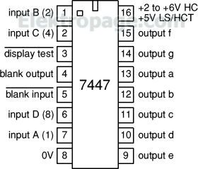
To
display the time as numerals we use the
7447 to connect 7490.
·
To
power on the 7447 pin-16 is connect to 5V and pin-8 to ground.
·
Connect
QA ,QB,QC and QD from 7490 to pin-7,1,2, &6 of 7447.
·
Connect
330Ω resistors to pins 13,12,11,10,9,15,14 of the 7447.
·
Connect
resistors through a, b, c, d, e, f & g segments to the 7-segmentLED.
·
Connect the common anode of the 7-Segment LED
to 5V.
To create the minute
hand section:

·
We
need duplicate “Second hand” portion to create the “Minute hand” section
·
To
create the “Hour Hand” portion we want to use an AND gate or inputs of the
7490.
·
After
recognizing the binary number 24 ,the hour counter reset to zero.
For a setting mechanism:-


·
For setting the clock ( digital clock system )
just move the input wires to drive higher- frequency signals into the
“minute-hand” section of the clock.
·
In
a real clock we use push buttons (or) switches and gates to do the same
operation (working).
·
In
clocks (or) watches for the alarm & other features we (connected) including
low-power chips.
·
The chip is probably embedded directly into
the circuit board.
Tqu mam
ReplyDeleteA digital clock uses electronic Host Genics components like oscillators, counters, and display drivers to measure and display time in a numerical format, typically driven by a quartz crystal for accuracy.
ReplyDelete