*** Explain I/O Programming (OR) Discuss about I/O
Programming

In 8051 there are four ports
for I/O operation. In 40 pins, 32 pins are set for the 4 ports P0 , P1,
P2 and P3. Each port takes 8 pins. When “0” is sent to
port, then it becomes an output . When “1” is sent to the port then it becomes
an input.
Port-0 (32 to 39 pins) can
be used as input or output. Port-0 must be connected externally to a 10KΩ pull-up resistor.

Port-0 as input : To make port-0
as input, by writing 1 to all the bits and then data is received from that port
and sent to P1. Get a byte from P0 and send it to P1.
MOV
A,#0FFH ; A=FFH
MOV P0,A ; make P0 an i/p port by writing all 1’s to it
Back : MOV A,P0 ; Get data from P0
MOV P1,A ; Send it to
port-1
SJMP
Back ; Keep doing it.
Dual role of Port-0 : Port-0 is also provides both
address and data when 8051 is connecting to an external memory. The 8051
multiplexes address and data through port-0 to save pins.
To toggle all bits of P0 continuously by 55H and AAH as
Toggle all bits of P0.
Back : MOV A,#55H ; A=55H
MOV P0,A
A CALL DELAY
MOV A,#0AAH
MOV P0,A
A CALL
DELAY
SJMP Back
Port-1 : (1 to
8)pins can be used as input or output. This port does not need any pull-up
resistors.Port-1 works as an input port by continuously send the code on port-1. The alternating values 55H and AAH.
To toggle all bits of P1 continuously by 55H and AAH as
Toggle all bits of P1.
MOV A,#55H ; A=55H
Back : MOV P1,A
A CALL DELAY
CPL A ; complement
register A
SJMP Back
Port -1 as input : To make port -1 as input port
,then must be writing 1 to all its bits, then data is received from that port
and saved in R7,R6 & R5 .
MOV
A,#0FFH ; A=FFH
MOV P1,A
: make P1 an i/p port by
writing all 1’s to it
MOV A,P1 ; Get data from P1
MOV R7, A ; Save it in register
R7
A CALL DELAY ; wait
MOV A,
P1 ; get another data
from port-1
MOV R6,A ;
save it in register R6
A CALL DELAY ; wait
MOV A, P1 get another data from port-1
MOV R5,A ; save it in register R5
SJMP
Back ; Keep doing it.
Port-2:(21
to28) . It can be used as I/P or O/P. Port-2 does not need any pull-up
resistors.
The following code will send out continuously to port-2 by the
alternating values 55H and AAH
i.e all
the bits of P2 toggle
continuously.
MOV A,#55H ; A=55H
Back : MOV P2,A
A CALL DELAY
CPL A ; complement register A
SJMP Back
Port -2 as input:
To make port-2 as an
input, it must programmed by writing 1 to all its bits. Then data is received
from that port and is sent to P1 continuously.
Get a byte from P2 and
send it to P1
MOV
A,#0FFH ; A=FFH
MOV
P2,A ; make P0 an i/p port by writing all 1’s to it
Back : MOV A,P2 ; Get data from P0
MOV P1,A ; Send it to
port-1
SJMP
Back ;
Keep doing it.
Dual role of port -2: In many systems P2 is used as simple I/O. When 8051/31 is
connected to external memory P2 is used for higher order address bus (A8 –A15).
When P0 provides lower 8-bit A0-A7 Address then P2 must be provide
upper 8-bit address lines A8 –A15 to access 64 Kbytes of external memory.
So normally P2 cannot be used for I/O.
Port-3 : (10
to 17). It can be used as input or output. P3 does not need any pull-up resistors. Port-3 is
used as some extremely important control signals as alternate functions.
P3.0 & P3.1 is used for the (RXD & TXD) Serial
communication signals.
P3.2 & P3.3 are used for external interrupts (INT0
bar,INT1bar).
P3.4 & P3.5 (T0 ,T1 ) are used
for Timer 0 & Timer 1.
P3.6 & P3.7 (WR bar, RD bar) are used to provide Read and
Write operations.
BY applying reset all ports have
value FFH. (1111 1111) on them. This makes
them input ports upon reset.
*** Discuss about I/O
Bit Manipulation Programming
I/O ports and bit addressability:
I/O bit Manipulation is a powerful and widely
used feature of the 8051 family.
When we need to access only 1 or 2
bits of the port instead of the entire 8-bits.
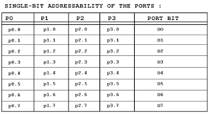
Then 4 ports (P0, P1,P2,
P3 ) can access either the entire 8-bits or any single bit without
altering the reset.
When accessing a Port in Single-bit
manner, we use the syntax SET B X.Y
Where X represents port number
0,1,2,3 and Y represents for bit number from 0to7 for data bits D0 to
D7
Eg: SET B P1.5 ; Sets bit 5 of Port-1
To toggle bit P1.2 continuously
Back : CPL P1.2 ; Complement P1.2 only
A CALL DELAY
S JMP BACK
Single bit – instructions:

*** Explain 8051 instruction set (OR) Explain classification of 8051
instructions
The 8051 instructions can be
classified into five groups.
1)
Data
transfer instructions
2)
Arithmetic
instructions
3)
Logical
instructions
4)
Branching
instructions
5)
Boolean
instructions

Data transfer instructions:
In 8051 microcontroller MOV, MOVC,
MOVX, PUSH, POP, XCH and XCHD
instructions are used to transfer data between registers and memory locations.
In 8051 microcontroller data transfer
operations are:
·
Copy
the content of a SFR to internal memory (OR) Vice versa.
·
Load
an immediate operand to SFR/internal memory.
·
Exchange
the content of SFR/internal memory with ACC.
·
Copy
the content of program memory to Accumulator.
·
Copy
the content of data memory to accumulator (OR) Vice versa.
Eg: MOV A,Rn
MOV A,direct
MOV A,@Ri
MOV A,#data
In 8051 Microcontroller we
perform addition, subtraction, multiplication, division ,increment and decrement operations on binary data.
The mnemonic used for arithmetic operations
are ADD, ADDC , SUBB, INC, DEC, MUL, DIV
and DA.
The result of most of the arithmetic operation
is stored in accumulator except a few decrement and increment operations.
Except increment and decrement instructions
all other arithmetic instructions are effected the flags of 8051.
Eg:
ADD A, Rn
INC @Ri
SUBB A,direct
DEC
Rn
MUL AB
DIVAB
Logical instructions:
In 8051 microcontroller we performing logical
AND , OR, EX-OR, Complement operations and Right, left rotating operations.
The mnemonic used for logical operations are
ANL, ORL, XRL, CLR , CPL, RL,RLC,RR, RRC and SWAP.
In logical operations only rotate
through carry operation is effected the flags of 8051.
In most
of the logical instructions the result is stored in accumulator and in some
instructions the result is stored in internal RAM/SFR.
Eg: ANL A, Rn ; logical operation is performing between A
& Rn
ORL A, # data
RRC
A
SWAP A
Program branching instructions:
Normally
a program is executed sequentially a PC (program counter) keeps track of the
address of instructions and it is incremented appropriately after each fetch operation.
There are two types of program branching
instructions
1.
Conditional
branching instruction
2.
Un
Conditional branching instruction
the condition in the instruction is true,
In Unconditional branching
instruction the pc is always modified.
The
instructions like ACALL & L CALL will save the previous value of Pc in
stack before modifying the Pc.
Eg:
JNZ offset, JZ OFFSET, LJMP 16-BIT, RET, NOP, RET1, DJNZ Rn,
offset.
Boolean variable instructions:
The
Boolean variable instructions operate on a particular bit of a data. This group include instructions which clear
complement or move a particular bit of bit addressable RAM/SFR or carry flag.
It
also include jump instructions which transfer the program control to a new
address if a particular bit is set or cleared.
The Boolean variable instructions of 8051 are
Eg: CLRC, SET B C, SET B bit, CPL C, CPL bit,
MOV
C , bit, JC offset, JNC etc


*** DISCUSS ACCESSING MEMORY USING VARIOUS ADDRESSING MODES:
We can use direct or register indirect
addressing modes to access data stored either in RAM or registers of the 8051
and also ON-Chip ROM containing data using indexed addressing mode.
Direct addressing mode:
There are 128 bytes of RAM in the 8051(from OOH to 7FH) This RAM can be
accessed using direct addressing mode.
Mostly 30 to 7FH RAM locations
are accessed by it. Register bank
locations are accessed by the register names of R0-R7. But there is no such name for other RAM
locations.
In
the direct addressing mode, the data is in a RAM address is known and this address is given as
a part of the instruction.

SFR REGISTERS AND THEIR ADDRESSES:
In
8051 registers A,B,PSW & DPTR are
part of the SFR. The SFR can be accessed by their names or by their addresses.
Eg:
Reg A address is EOH and register B address is FOH. Then we write instructions as
MOV OEOH,
#5H ( OR ) MOV
A, #55H
The special function register address
is between 8OH to FFH
Not all the address space of 80 to FF
is used by the SFR. The unused locations
in 80H to FFH are reserved and must not be used by the 8051 programmer.
In
direct address mode, the address value is limited(00H to FFH) to access RAM locations and registers located
inside the 8051.
STACK IN DIRECT ADDRESSING MODE:
The
major use of direct addressing mode is stack.
In 8051 family only direct addressing mode is used to PUSH and POP the
stack by their register addresses.
REGISTER INDIRECT ADDRESSING MODE:
In
register indirect addressing mode a register is used as a pointer of the
data. Registers RO & R1
are used for this purpose.
R2 to R7
cannot be used to locate the RAM. They must be represented by the “@” sign.
One of the advantage of register
indirect addressing mode is that it makes accessing data dynamic rather than
static.
Looping
is not possible in direct addressing mode, it is possible only in Indirect
addressing mode. This is the difference
between the direct& register indirect addressing mode.
In
register indirect addressing mode, to accessing any information in internal RAM
is limited because only two registers RO&R1 are used in
it.
To
accessing externally connected RAM or ON-chip ROM we need a 16-bit
pointer. In such cases the DPTR register
is used.

INDE XED ADDRESSING MODE AND ON-CHIP ROM ACCESS:
Indexed
addressing mode is widely used in accessing data elements of look up table is
located in 8051 program ROM.
MOVC
A, @A+DPTR
Instruction is used for this purpose. The 16-bit register DPTR and register A are
used to form the address of the data element stored in ON-CHIP ROM.
The instruction MOV C is used instead of MOV.
The “c” means code. In this instruction
the contents of A are added with DPTR to
form the 16-bit address of the needed data.
Program
counter is another register used in Indexed addressing mode. The 8051 has another 64k bytes of memory
space set for data storage i.e., data memory.
This external memory is accessed only by the MOV X instruction.

*** Explain 8051 ADDRESSING MODES:
The
CPU can access data in various ways i.e., in a register(or) be provided as an
immediate value. These various ways of
accessing data are called addressing modes.
The
8051 provides a total of five addressing modes.
They are
1
Immediate
addressing mode
2
Register
addressing mode
3
Direct
addressing mode
4
Register
indirect addressing mode
5
Indexed
addressing mode


1.
IMMEDIATE ADDRESSING MODE:
In
immediate addressing mode an 8/16 bit immediate data/constant is specified in
the instruction itself.
The
immediate data must be expressed as pound sign i.e., #
This
addressing mode is used to load information into any of the register including
the DPTR register.
We can also use immediate addressing mode to send data to 8051 ports.
We can also use immediate addressing mode to send data to 8051 ports.
When
8051 executes an immediate data. Program
counter is automatically incremented.
Eg: MOV A,#25H
MOV R4,#56H
MOV DPTR,#5467H
MOV DPL,#48H
MOV DPH,#87H
2.REGISTER ADDRESSING MODE:
In
register addressing mode, the instruction will specify the name of register as
a operand. In register addressing mode. Register A, DPTR and R0 to R7
are used in the part of a mnemonic as source or destination.
Eg: MOV A,R0
MOV A,R7
ADD A,R5
We
can move the data between accumulator and Rn registers. But data will not move in between Rn
registers.
Eg: MOV R4,R7 is invalid.


3.DIRECT ADDRESSING MODE:
In direct addressing mode, the address of the data is directly specified in the instruction. The direct address can be the address of an internal RAM location(00H T07FH) or address of a special function register(80H to FFH).
In direct addressing mode, the address of the data is directly specified in the instruction. The direct address can be the address of an internal RAM location(00H T07FH) or address of a special function register(80H to FFH).
Eg: MOV R0, 40H
MOV OE0H, #55H
MOV A, #55H
MOV OE0H, R2
MOV 56H,A
The
SFR can be accessed by the names or by their addresses.

The
major use of direct addressing mode is the stack. In 8051 family, only direct addressing mode
is allowed for pushing onto the stack.
Therefore “PUSH A” instruction is invalid.
Pushing
the accumulator onto the stack must be coded as “PUSH OEOH”. Similarly pushing R3 of bank0 is coded as “PUSH 03”.
For
the pop instruction to pop the top of the stack into R4 of bank 0 we
use “POP 04” instructions.
4.
REGISTER INDIRECT ADDRESSING MODE:
In
the register indirect addressing mode, a register is used as a pointer to the
data. If the data is inside the CPU,
only registers R0 and R1 are used for this purpose.
When
R0 and R1 are used as pointers then “@” sign must be used, to address only for
the internal RAM locations (00H TO 7FH).
The external RAM can be addressed indirectly through DPTR.
Looping
is not possible in direct addressing mode and it is possible in Indirect
addressing mode.
Eg: MOV A,@R0
MOV @R1, B
5.INDEXED ADDRESSING MODE:
Indexed
addressing mode is widely used in accessing data elements of look up table
entries located in the program ROM space of the 8051.
The
instruction used for this purpose is MOVC A, @A+DPTR.
The 16-bit register DPTR and register
A are used to form the address of the data element stored in on-chip ROM.
Because
the data elements are stored in the program(code) space ROM of the 8051. The instruction MOV C is used instead of
MOV. The “c” means code.
In
this instruction the contents of A are added to the 16-bit register DPTR to
form the 16-bit address of the needed data.

Very, good
ReplyDelete